Software Rendering
Software rendering for 2D graphics can be a simple affair, implemented just by copying sections of preloaded images to the framebuffer. So called spritesheets contains the individual frames of animated objects. Tilesets contains the building blocks of static surroundings.
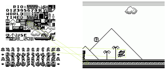
Font Rendering
Font rendering is a similar process using images that contain individual letters and can be used the same way as a tileset. But font rendering can also be considerably more advanced. Fonts as used in today’s operating systems (TrueType fonts) are defined by line segments and Bezier curves and contain lots of additional data like kerning data (for letter combination specific positioning) and hinting information for pixel snapping (shifting font positions slightly to better align with the pixel grid). Additionally, modern font renderers consider the positions of the rgb subpixels of the monitor to increase horizontal rendering resolution. All of those additional details are costly, especially for game renderers which are optimized to rerender everything every frame. Games usually end up prerendering modern fonts to images to use traditional and fast image-based font rendering at runtime.
Advanced 2D Rendering
More advanced 2D games scale and rotate images. To do that, image data cannot simply be copied but has to be sampled. A rotated or scaled image is still a rectangle that can be drawn line by line. For every drawn pixel the portion of the width and height of the rectangle at which the current pixel is drawn multiplied by the width and height of the image results in an x and y index that can be used to take a pixel out of the image. This procedure is called point sampling.
Raycasting
3D games gained massively in popularity when they started to sample images. At the forefront of that development were games like Catacomb 3D and Doom which made use of an algorithm called Raycasting. For every calculated screen column Raycasting checks a ray from the camera position through the column against a structure representing the current game level. That structure is a collection of walls and when a ray hits a wall, that column is filled with one column of the image which belongs to that particular wall. The hit position is used to calculate an x sample position. This algorithm does not consider heights and can therefore only be used to calculate what looks like a 3D representation of a fundamentally 2D game in the style of early top-down games like Gauntlet and Alien Breed.
Raytracing
Raycasting can be generalized to work on lines and columns as well as all kinds of 3D objects which is then called Raytracing. For every pixel of the screen a ray from the camera position through the corresponding pixel is checked for collisions with every object in the 3D scene. Raytracing was actually used long before the invention of Raycasting but still today difficult to make a Raytracer run fast enough for realtime graphics. Jumping around wildly in memory for every pixel to calculate collisions with every scene object is especially impractical for modern computers which have very slow memory access times compared their pure calculation speeds.
Rasterisation
The actual algorithms used for today’s 3D games (and for earlier 3D games that were around before Raycasting was introduced) are simpler and more iterative. Instead of providing the renderer with some kind of a complete scene description, 3D games are rendered one primitive (mostly triangles) at a time. 3D objects are simply arrays of primitives – more exactly a 3D object, commonly called a mesh, is an array of 3D coordinates/vertices and an array of indices of coordinates, forming the primitives. The vertex array often contains additional data like image sample coordinates. The coordinates are transformed according to the current camera position and the resulting positions are used to draw the primitives.
foreach (tri in world) {
	Point p1 = transform(tri._1);
	Point p2 = transform(tri._2);
	Point p3 = transform(tri._3);
	drawTriangle(p1, p2, p3); // 2D operation
}
3D transformations happen in three steps: Applying camera translation, applying camera rotations and applying a perspective projection. Applying camera translations happens the same way as in a 2D game – when the camera moves to the left, everything on screen moves to the right.
x = vertex.x - camera.x
y = vertex.y - camera.y
z = vertex.z - camera.z
Rotations can be best understood by rotating a coordinate system and calculating the positions in the new coordinate system.
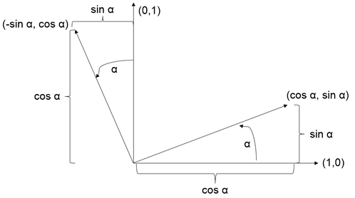
The rotated positions can be calculated by multiplying the original positions with the axes vectors of the coordinate system. (x,y) = x(1,0) + y(0,1) For a rotated coordinate system this results in:
R(x,y,α) = x(cos α, sin α) + y(-sin α, cos α)
              = (x cos α, x sin α) + (-y sin α, y cos α)
              = (x cos α - y sin α, x sin α + y cos α)
A camera in 3D space can be rotated around three axes, which can be handled by rotating around each axis one after another. The last step, the perspective projection is surprisingly easy.
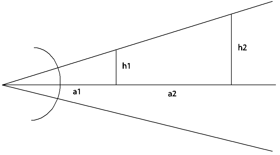
The picture shows a typical system of lenses like a camera or an eye. Comparing the triangles one can assess that
h1 / a1 = h2 / (a1 + a2)
which means that an object at double the distance from the camera has half the projected size. Introducing a plane of constant z values at which an object is projected at its original size the perspective projection transformation is
x = (zmin / distance) / vertex.x
y = (zmin / distance) / vertex.y
Taking all of that into account and moving the 0 position to the middle of the screen yields the following algorithm:
float dx = X - camera.x;
float dy = Y - camera.y;
float dz = Z - camera.z;
float d1x = cos(camera.ry) * dx + sin(camera.ry) * dz;
float d1y = dy;
float d1z = cos(camera.ry) * dz - sin(camera.ry) * dx;
float d2x = d1x;
float d2y = cos(camera.rx) * d1y - sin(camera.rx) * d1z;
float d2z = cos(camera.rx) * d1z + sin(camera.rx) * d1y;
float d3x = cos(camera.rz) * d2x + sin(camera.rz) * d2y;
float d3y = cos(camera.rz) * d2y – sin(camera.rz) * d2x;
float d3z = d2z;
Xp = (zmin / d3z) * d3x + screenWidth / 2
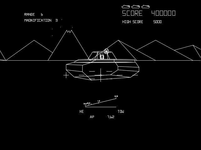
When the coordinates are transformed, the individual points can be connected using a line drawing algorithm like DDA or Bresenham. Early 3D games used line drawing exclusively, although those games originally didn’t use any line drawing algorithms but instead used so called vector displays.
Later 3D games as well as today’s 3D games used not only lines but mainly triangles or quads. Today’s hardware is optimized for triangle drawing though in the mid-90s some hardware was optimized for quad drawing. After the tree points defining a triangle have been transformed the triangle can be drawn using the new points. This is a 2D operation, the z coordinate can be ignored at that point. Triangles can be drawn line by line, using a so-called scanline algorithm. To draw a triangle, find the longest edge on the monitor’s y axis. Iterate over y and fill all lines between the long edge and one of the other edges. Repeat with the long edge and the remaining edge.
That is sufficient for drawing triangles, but drawing an actual mesh will show depth sorting problems – some triangles from the backside of the object will show up on top of other triangles. A first step to help with depth sorting and also increase performance is backface culling, removing any triangles that do not face the camera. A fast backface culling procedure is to require mesh data to contain triangles with constant winding and calculate winding after transformation using a cross product of two of the triangle sides. The resulting, perpendicular vector will show to or from the camera depending on its winding.
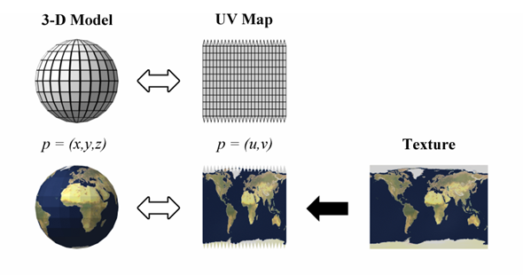
As mentioned before, 3D graphics became big, when images were applied to the somewhat dull looking triangles. The process is essentially the same as for scaled and rotated 2D graphics. Mesh data is accompanied by additional image coordinates which are numbers between zero and one describing what part of the image is to be applied to the triangle corner. During triangle rasterisation those image coordinates are interpolated and corresponding image values are sampled.
Depth can also be handled in the same way it’s done in 2D games – drawing complete objects from farthest to nearest. In combination with backface culling scenes consisting of simple 3D objects can be drawn correctly. This however cannot properly handle object intersections and more complex 3D objects which contain overlapping layers (for example an ear on a head).
Culling
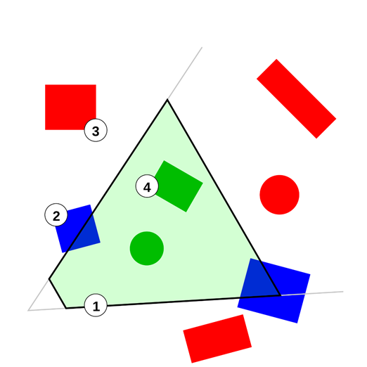
To further enhance performance, games try to only draw objects that are actually visible. This is especially important for a software renderer. An easy and generally useful optimization is frustum culling, which tests every object against the view frustum. The view frustum as defined by the screen boundaries, a minimal z value and eventually a maximum z value consists of six planes. An object which is on the back of all of those planes is out of view.
More complex object culling algorithms include building recursive scene structures like octrees or more game specific algorithms as applied in the Quake series, which’s levels are defined by rooms which are connected by windows. Every frame the game checks all windows of the current room and then renders the current room and all visible neighbor rooms. However as CPUs become ever speedier and memory accesses become costlier it becomes more effective for many games to just iterate over an array of every object instead of using some form of hierarchical object tree. It can also be beneficial to do more involved calculations to figure out which objects are inside the view frustum but completely occluded by other objects. But this can get be very complex and depends largely on the typical level structure of a specific game whether such algorithms are beneficial. For static objects visibility data can be precalculated, for more dynamic games, scenes can be rasterizing using a low complexity version of the game world to check for visibility before the actual high quality rendering. Modern graphics chips support occlusion queries, to help out with this process – however this requires expensive CPU<->GPU communication for which reason actual CPU rasterisation can be a useful alternative.