Bumps and Animations
Bump Mapping
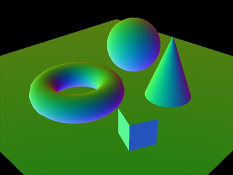
Bump Mapping describes a number of methods which are used to add the appearance of geometric detail to a surface without actually adding additional polygons. As such, bump mapping is generally implemented in the fragment shader. Today’s most used variation of bump mapping is normal mapping, which uses a texture which encodes a normal vector in each pixel.
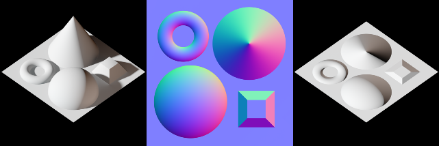
Those normals can be defined in object space, which makes rendering easy (they can just be transformed with the positional data) but won’t work when the mesh is animated. Therefore normals in a normal-map are normally defined in tangent space – a local coordinate system for each vertex, perpendicular to the surface and aligned to the regular texture coordinates.
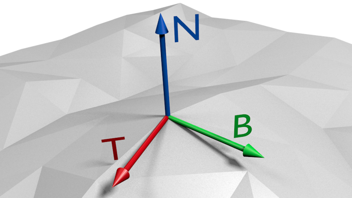
One axis of tangent space is defined by the normal of the vertex. The other two axes can be calculated based on the uv and positional differences in a triangle based on the equations
deltaPos1 = deltaU1 * T + deltaV1 * B
deltaPos2 = deltaU2 * T + deltaV2 * B
The three axes yield a matrix which can be used to transform data to and from tangent space. In tangent space the sampled normal from the normal-map can be with the regularly interpolated normals of the mesh by adding and renormalizing the normals. Further lighting calculations are then done as they are normally done.
Normal maps work best when seen from the front. When a surface is seen at a steep angle the actual outline of the surface becomes visible, exposing any missing geometry when normal-maps are used to model bigger details. As such normal-maps should preferably be used for small geometric details that would hardly be visible in the outline of a surface.
Parallax Mapping
More complex methods than normal mapping exist that do some actual perspective 3D calculations on a surface.
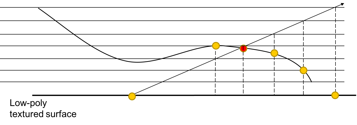
What the usual texture mapping and normal mapping cannot handle is parallax. If a surface is not flat (if it were, we could just skip normal mapping altogether), we would experience parallax due to the varying heights. Since we only have flat polygons, we will not sample the texture of the polygon at the correct position based on the height. The goal of all Parallax Mapping methods is then to find the correct offset to sample the texture at the correct position.
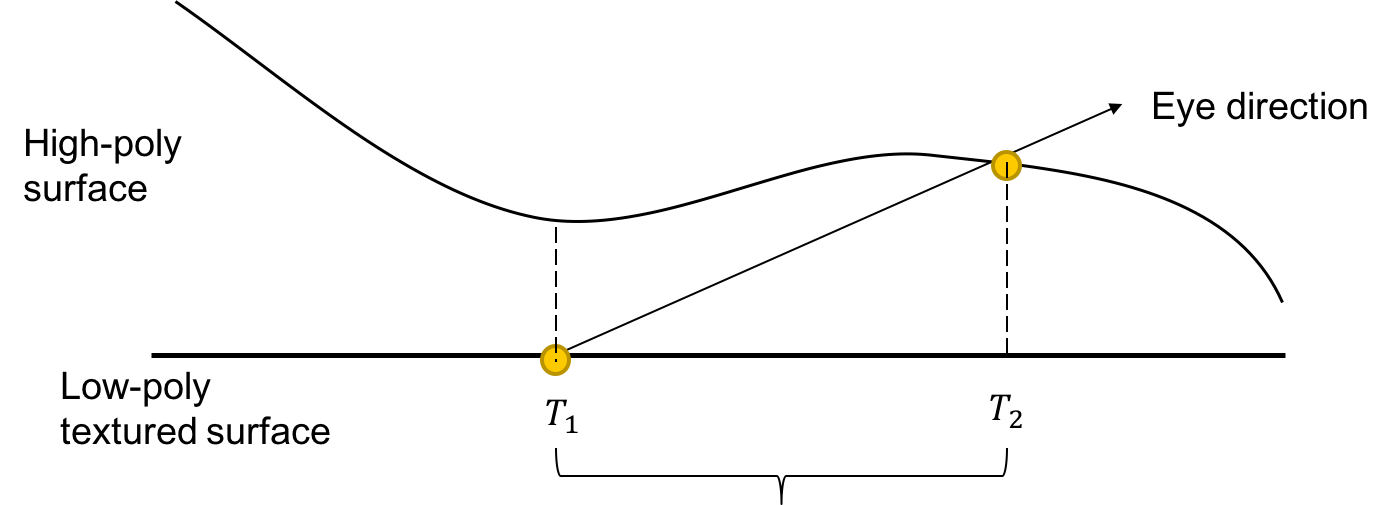
All parallax mapping algorithms use a height map, a texture with values between 0 and 1 encoding the heights of the pixels.
The original parallax mapping algorithm tries to estimate the offset in one step. It retrieves the height from the height map at the point that is sampled originally (T1 in the image above) and finds out where it intersects the plane at the height of the pixel.
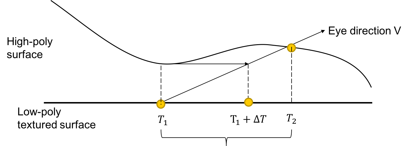
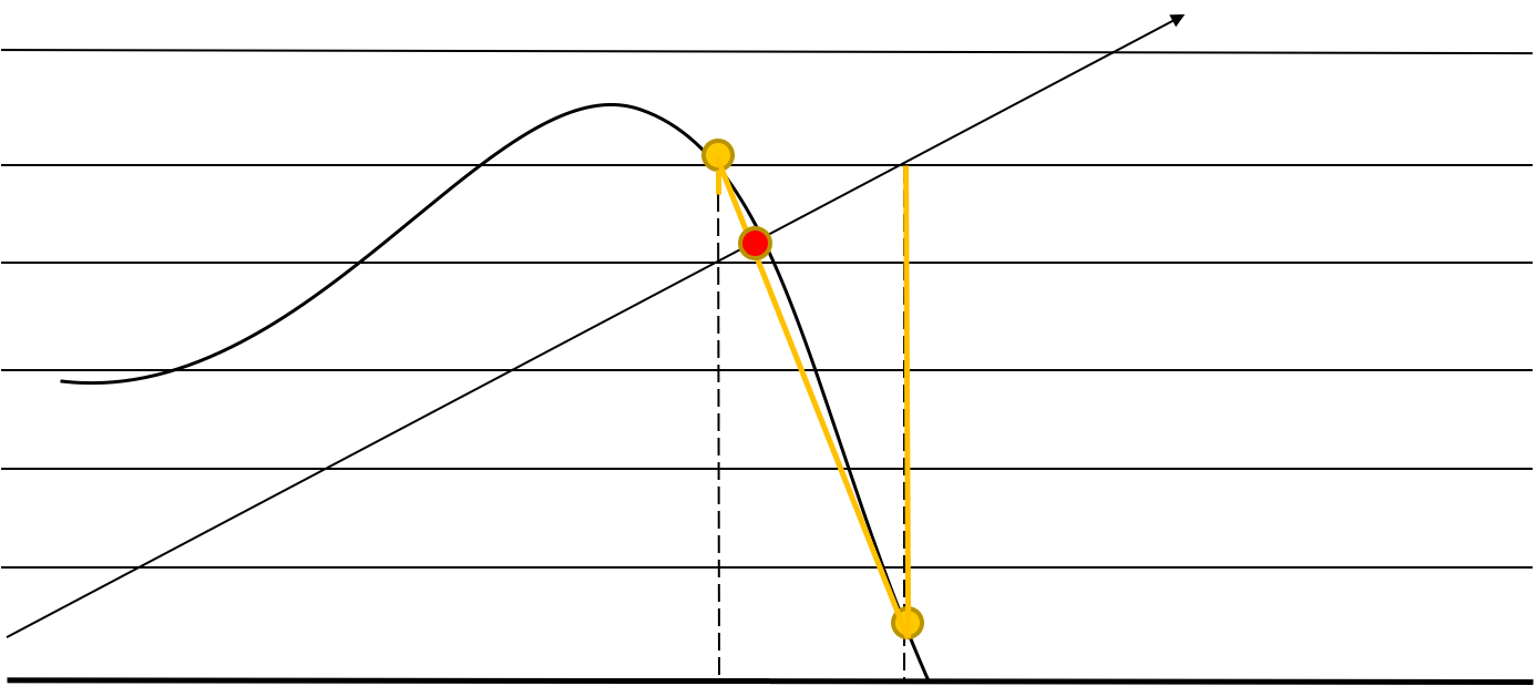
The successors of Parallax Mapping in general use several steps to get a better estimate of the offset. Steep Parallax Mapping divides the heights into layers and checks the layers until an intersection with the height map is found.
Parallax Occlusion Mapping uses the last two points found by steep parallax mapping and interpolates between them.
Displacement Mapping
Displacement mapping is an even easier method that uses a texture which encodes additional height data. Vertices are displaced based on the texture data. Displacement mapping is mostly interesting when vertices are created adaptively at positions where height changes faster and/or where parts of the mesh are closer to the camera. Some form of displacement mapping is often used to display hilly landscapes. Using modern graphics chips adaptive displacement mapping can be implemented using tessellation shaders.
Forward Shading
Forward shading refers to the “usual” way of rendering images. In forward shading, we set up shaders, send all geometry to the graphics card, then geometry is drawn. If we have several images in the scene, we can batch them to a certain degree by supplying several lights to one shader, but there are limits set by APIs and GPUs. If we want to render more lights, we have to render the whole scene several times and add up the individual images. This approach is costly for a large number of lights.
Deferred Shading
Normal mapping brought up an alternative rendering technique called Deferred Shading that is in some form used in most modern 3D engines. Deferred Shading splits rendering in two steps. In the first step scene data is rendered to multiple buffers, creating a color map, a normal map and a depth map of the viewport.
Lighting calculations happen in a second step based on the prerendered maps and strictly per pixel. Deferred Shading makes it easier to limit lighting calculations to actually affected pixels and is generally combined with some method to estimate what sections of a scene are influenced by a specific light, which can for example be done by using occlusion queries based on light volumes.
Matrix Animations
The model matrix typically assigned to each scene object can be used to implement some simple animations. Transformation matrices as seen earlier can support translations, rotations, scaling and shearing and all of that can be combined and changed over time to move and animate objects. It is highly important to combine transformations correctly by multiplying transformation matrices in the correct order. Rotation, scaling and shearing is based on the origin of the current coordinate system and it is often necessary to prepend a translation to all further transformations for them to happen at the correct origin while later adding the inverse of the translation to move the object back to its expected position.
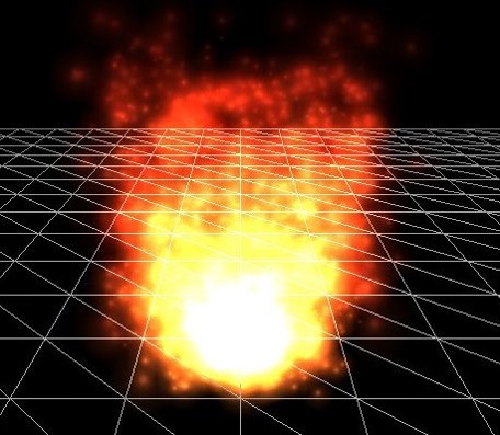
Particle Systems
Particle Systems are systems of usually small objects, mostly just images, which are animated using transformation matrices. Additionally in most particle systems transparency values are changed over time to let individual particles disintegrate smoothly. The effects of particle systems are based on high particle numbers.
Simple images in 3D scenes such as the ones used in most particle systems are call billboards and are mostly implemented by rendering a texture across two triangles which always rotated to the camera. The inverse of the view matrix contains the necessary rotations.
Particle systems define an origin point called the emitter. Particles start at that position with an initial speed and are moved around using simple physics.
Particles typically do not interact with each other which makes calculating particle systems fast. Interacting particles however can be used to implement fluid or gas simulations by calculating the forces between particles, identifying larger blobs of particles and drawing a meshes which enclose those blobs. Calculating interactions between objects is an O(n^2) operation when implemented naively which is not acceptable for larger numbers of particles. Dividing a scene in grids and only calculating interactions of particles which lie in the same grid can reduce the number of calculations sufficiently.
![]()
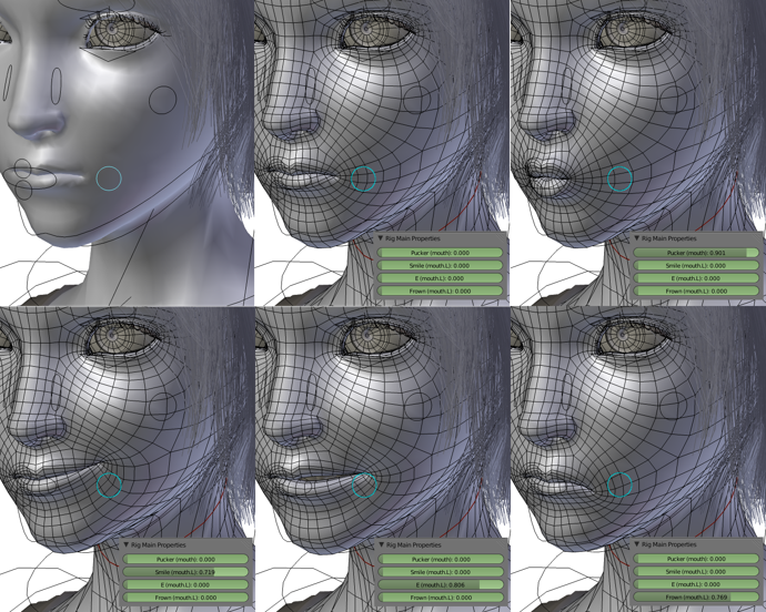
Morph Target Animation
Sprite animations in 2D games are done using lots and lots of slightly different copies of the same image and switching between them over time.
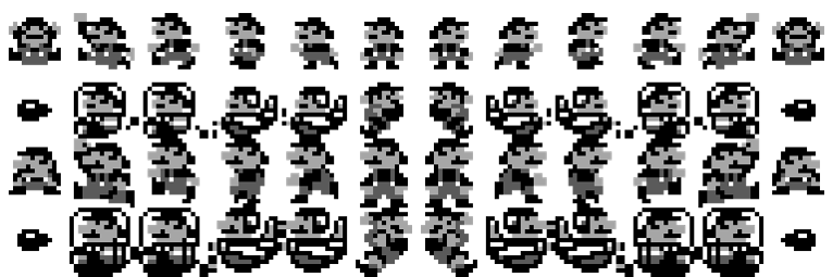
The same can be done in 3D (for example, the original Quake used this method of animation), but quickly leads to uncomfortably large amounts of data. Reducing the number of frames and interpolating between those works well for some kinds of objects but doesn’t yield good results when used to animate objects which originally move based on joint systems like humans do. Interpolating vertex positions works for faces though, which are often animated by defining frames for some extreme face positions (like completely opened or closed mouth) and interpolating between those. By capturing frames for phonemes faces can also be semi-automatically animated based on voice data.
Skeletal Animation
By far the most used animation technique in 3D games is skeletal animation, which defines a skeleton as a tree structure of joints, representing each joint using a transformation matrix. The actual animation can then be reduced to a small array of transformation matrices. Because most life forms move purely using rotational joints the animation data can be further reduced to just an array of rotations. But skeletal animation not only reduces the necessary data set dramatically, it is also an accurate representation of how most life forms actually move and can therefore easily be used for some kinds of procedural animation – for example rotating a head to make a character look at a specified spot. Also interpolation joint rotations works just fine.
Apart from zombie games though it is mostly not sufficient to just move skeletons around, because skeletons are generally surrounded by flesh which surrounds the skeleton and is deformed smoothly according to the joint positions. Skinning is a method used to surround a skeleton with a deformable mesh.
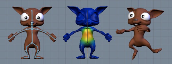
To prepare the mesh for the possible deformations a weight parameter is defined for each pair of vertices and joints. This dataset can be reduced by only considering the N strongest weights for each vertex. This adds a (weight, index) array to each vertex. To compute the deformations when the model is loaded the inverse of each joint transformation is precalculated in model space. When the model is animated the transformation matrices in model space are recalculated for each joint. The transforms which are then used to deform the mesh are calculated by multiplying the current model space transformations of each joint with their precaculated inverse transformations. For each vertices those transformations are applied according to the supplied weights and summed up, creating a weighted average of the vertex positions calculated based on the individual joints.
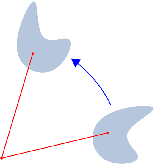
Animating based on presupplied transformations is called Fordward Kinematics. The inverse process, supplying a target position and calculating the joint transformations so that a specific vertex ends up at the target position, is called Inverse Kinematics. Inverse Kinematics have to be calculated using numerical optimization methods, incorporating constraints for the rotation angles actually supported by individual joints. Inverse Kinematics are a pivotal topic in Robotics.
Weighted and linearly interpolated skinning can introduce artifacts because it generally does not keep the volume enclosed by the deformed mesh constant. This is mostly visible at narrow angles like at the arm pits. This problem is commonly referred to as the “candy wrapper problem”.
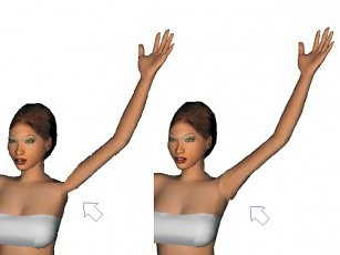
Implementing spherical skinning efficiently to avoid these artifacts is a topic of active research.
Skinning algorithms also do not take care of muscle movements, which makes shirtless muscular characters as they tend to be used in games look even stiffer than they are supposed to look. Some games interpolate several normal maps while animating a character to somewhat offset that effect.
Root Motion
With skeletal animation, we have two possibilites:
- We encode the motion of the whole character as the translation animation of the root bone of the character. This is referred to as “root motion”. The advantage of this approach is that speeds are encoded directly into the animation, and effects like accelerations are accurate. Also, problems like footskating (the character’s feet move while they should be fixed on the ground during walking) can be avoided. The disadvantage is that there is little control during runtime, since all motion information is encoded in the animations. Furthermore, usually more animations are required. Also, the speed is fixed, and new animations have to be prepared if the speed is intended to be changed.
- We do not animate the translation of the root bone. In this version, the character stands in place, therefore, the overall translation has to be done separately. We have more control over this, can for example also animate it physically. On the flip side, problems like foot skating can be present.
Physical Animation
Actual muscle and fat simulations are rarely seen in games due to performance constraints. There are some notable but mostly weird exceptions.
Increasingly though hair and cloth are animated by applying physics simulations. Characters themselves can also be animated automatically because a skeleton represents the actual inner workings of a character well. This however only works properly when a character is unconscious – otherwise animations would have to be triggered by a KI systems which are generally not yet sufficiently advanced to convincingly animate a complete character. Accordingly modern games try to blend predefined and physical character animations depending on the current situation of the character.